How to Test a 123ignition
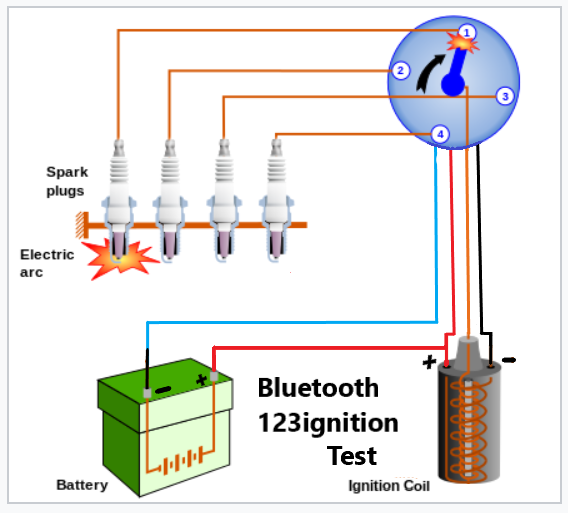
Bench Testing a 123 Ignition

-the +12V of the red wire is not connected on the coil +12V and this point gets interrupted by the ignition key when the starter is engaged
-bad connections in the wires and or high resistance in the ignition key lock*)
-bad grounding of the 123 unit *) in the engine block (I suggest using the M6 hole to attach an extra ground wire to the block)
-the spring loaded center graphite contact has fallen out of the distributor cap or is stuck in its hole and its spring does not push the pin against the rotor arm
-spark-plug leads or and or coil that with not enough isolation *)
*) Due to automatic coil current control and faster charge of the coil, peak currents in the low voltage circuit are higher and resistances can cause problems. The higher spark voltages in the HT circuit require better isolation in the HT leads and coil.
Testing the Injector outputs on IE Models
Injector Output Test – Yellow and White wires on IE models
Please be very careful with the white and yellow IE outputs.
These are common emitter outputs, this means they make connection with ground (-) or are open terminals.
If you connect these wires to the +12 volt, the circuit will get damaged immediate.
You could test as follows:
Take a LED and a resistor of 1k Ohm.
Make a connection from the + 12 Volt battery to the 1k Resistor.
Make a connection from the resistor to the Anode of the LED.
Make a connection from the Cathode of the LED to one of the IE wires of the distributor.
Rotate the ignition and the LED will flash.